Shift Cable Replacement
- Raise the vehicle on a lift, or apply the parking brake, block the rear wheels, and raise the front of the vehicle. Make sure it is securely supported.
- Remove the dashboard center lower cover (see DASHBOARD CENTER LOWER COVER REMOVAL/INSTALLATION
) and the dashboard center panel (see DASHBOARD CENTER PANEL REMOVAL/INSTALLATION
).
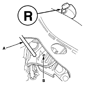
- Move the shift lever into R.
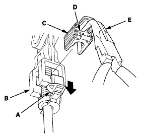
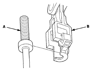
- Slide the lock tab (A) down on the shift cable end holder (B).
 Courtesy of AMERICAN HONDA MOTOR CO., INC.
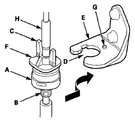
- Grasp the shift cable lock (C) in the middle (D) using angle-jaw needle-nose pliers (E), and remove it from the shift cable end and the shift cable end holder. Do not pry the shift cable lock using a screwdriver, it may damage the shift cable end holder.
- Separate the shift cable end (A) from the shift cable end holder (B).
 Courtesy of AMERICAN HONDA MOTOR CO., INC.
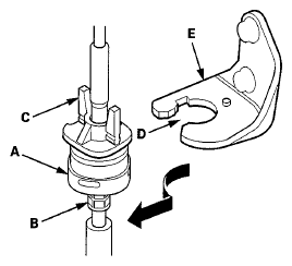
- Rotate the socket holder (A) on the shift cable (B) a 1/4 turn; the guide tab (C) on the socket holder will be perpendicular to the opening (D) of the socket holder bracket (E). Then slide the socket holder to remove the shift cable from the socket holder bracket.
 Courtesy of AMERICAN HONDA MOTOR CO., INC.
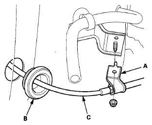
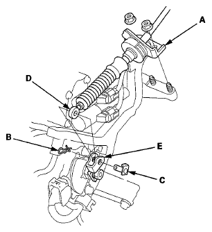
- Remove the shift cable bracket (A) and the grommet (B), and pull out the shift cable (C).
 Courtesy of AMERICAN HONDA MOTOR CO., INC.
- Remove the nuts securing the shift cable bracket (A).
 Courtesy of AMERICAN HONDA MOTOR CO., INC.
- Remove the spring clip (B) and the control pin (C), then separate the shift cable end (D) from the selector control lever (E).
- Install a new shift cable through the grommet hole. Do not bend the shift cable excessively.
- Install the shift cable bracket on the body, and install the grommet in its hole.
- Check that the transmission is in the R position at the selector control lever.
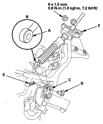
- Apply molybdenum grease to the hole in the bushing (A) in the shift cable end (B). Attach the shift cable end to the control lever (C), then insert the control pin (D) into the control lever hole through the shift cable end, and secure the control pin with the spring clip (E).
 Courtesy of AMERICAN HONDA MOTOR CO., INC.
- Secure the shift cable bracket (F) with the nuts.
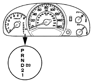
- Turn the ignition switch to ON (II), and check that the R position indicator comes on.
 Courtesy of AMERICAN HONDA MOTOR CO., INC.
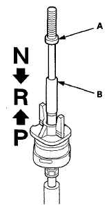
- If necessary, push the shift cable (A) until it stops, then release it. Pull the shift cable back one step so that the shift cable is in the R position. Do not hold the shift cable guide (B) to adjust the shift cable.
 Courtesy of AMERICAN HONDA MOTOR CO., INC.
- Turn the ignition switch to LOCK (0).
- Insert a 6.0 mm (0.24 in) pin (A) into the positioning hole (B) on the shift lever bracket base and through the positioning hole on the shift lever. The shift lever is secured in R.
 Courtesy of AMERICAN HONDA MOTOR CO., INC.
- Rotate the socket holder (A) on the shift cable (B) to place the guide tab (C) on the holder will be perpendicular to the opening (D) in the socket holder bracket (E). Align the holder with the opening in the bracket, then slide the holder into the bracket. Rotate the holder a 1/4 turn until the holder lock (F) stops at the locking pin (G) to secure the shift cable. Do not install the shift cable by twisting the shift cable guide (H).
 Courtesy of AMERICAN HONDA MOTOR CO., INC.
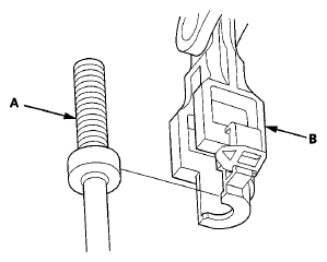
- Install the shift cable end (A) in the shift cable end holder (B). Keep the shift cable end and the shift end holder free of grease.
 Courtesy of AMERICAN HONDA MOTOR CO., INC.
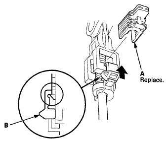
- Install a new shift cable lock (A) to secure the shift cable end and the shift cable end holder, then push the lock tab (B) up until it stops to lock the joint.
 Courtesy of AMERICAN HONDA MOTOR CO., INC.
- Remove the 6.0 mm (0.24 in) pin that was installed to hold the shift lever.
- Shift the shift lever to each position, and check that the A/T gear position indicator follows the transmission range switch.
- Install the dashboard center lower cover (see DASHBOARD CENTER LOWER COVER REMOVAL/INSTALLATION
) and the dashboard center panel (see DASHBOARD CENTER PANEL REMOVAL/INSTALLATION
).