Vehicle Speed Sensor Replacement
- Remove the air cleaner (see
AIR CLEANER REMOVAL/INSTALLATION
).
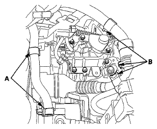
- Remove the heater hose clamps (A) and the IMA motor power cable clamps (B) from the bracket.
 Courtesy of AMERICAN HONDA MOTOR CO., INC.
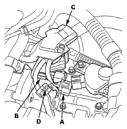
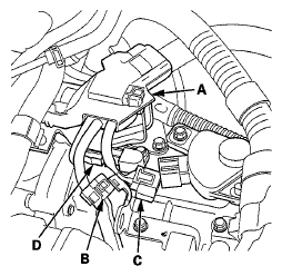
- Disconnect the transmission range switch connector (A) and the CVT output shaft (driven pulley) speed sensor connector (B).
 Courtesy of AMERICAN HONDA MOTOR CO., INC.
- Remove the harness clamp (C) and the harness holder clamp (D) from the harness clamp bracket.
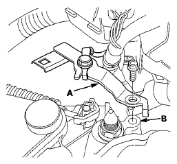
- Remove the ground terminal bracket (A) from the transmission mount (B).
 Courtesy of AMERICAN HONDA MOTOR CO., INC.
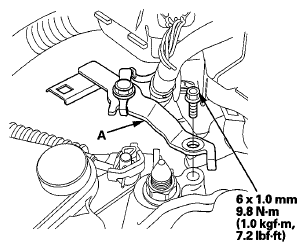
- Remove the harness clamp bracket (A).
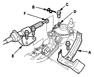
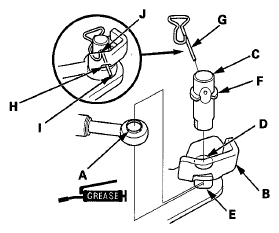
- Remove the snap pin (B) and the control pin (C) from the control lever (D).
 Courtesy of AMERICAN HONDA MOTOR CO., INC.
- Remove the bolts securing the shift cable holder (E), then separate the shift cable (F) from the control lever.
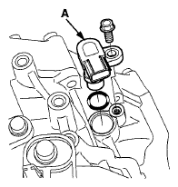
- Disconnect the vehicle speed sensor connector, and remove the vehicle speed sensor (A).
 Courtesy of AMERICAN HONDA MOTOR CO., INC.
- Install a new O-ring (B) on a new vehicle speed sensor, then install the vehicle speed sensor in the transmission housing.
- Check the connector for rust, dirt, or oil, and clean or repair if necessary, then connect the connector securely.
- Apply molybdenum grease to the hole in the shift cable end collar (A). Attach the shift cable end to the selector control lever (B). Insert the control pin (C) through the selector control lever hole (D), through the shift cable end hole, and into the selector control lever slotted hole (E) in the direction shown. Push the control pin until its flange (F) contacts the selector control lever surface.
 Courtesy of AMERICAN HONDA MOTOR CO., INC.
- Insert the snap pin (G) in the direction shown through the control pin hole and out the opening (H) of the selector control lever so that the hooked end (I) of the snap pin snaps into the countersunk hole (J) of the control pin.
- Secure the shift cable holder on the transmission with the bolts.
- Install the harness clamp bracket.
- Install the ground terminal bracket (A).
 Courtesy of AMERICAN HONDA MOTOR CO., INC.
- Install the harness clamps (A) and the harness hold clamp (B).
 Courtesy of AMERICAN HONDA MOTOR CO., INC.
- Connect the transmission range switch connector (C), and the CVT output shaft (driven pulley) speed sensor connector (D).
- Install the heater hose clamps (A) and IMA motor power cable clamp (B).
 Courtesy of AMERICAN HONDA MOTOR CO., INC.
- Install the air cleaner (see
AIR CLEANER REMOVAL/INSTALLATION
).