Relay And Fuse Block Removal/Installation: Notes
- Remove the battery tray. (See
BATTERY REMOVAL/INSTALLATION [SKYACTIV-G 2.0, SKYACTIV-G 2.5]
.)
- Remove the air cleaner case. (See
INTAKE-AIR SYSTEM REMOVAL/INSTALLATION [SKYACTIV-G 2.0, SKYACTIV-G 2.5]
.)
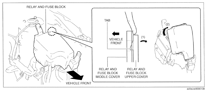
- While pressing the relay and fuse block upper cover tab in the direction of the arrow (1) shown in the figure, lift up the relay and fuse block upper cover in the direction of the arrow (2) to detach the relay and fuse block upper cover tab from the relay and fuse block middle cover.
 Courtesy of MAZDA MOTORS CORP.
- Remove the relay and fuse block upper cover.
- Remove all the relays and fuses.
CAUTION:
- If the relay and fuse block is removed with the relays and fuses installed, the area around the relay and fuse block may contact the relays or fuses and damage the them. Before removing the relay and fuse block, remove all the relays and fuses.
- Remove the front body control module (FBCM). (See
FRONT BODY CONTROL MODULE (FBCM) REMOVAL/INSTALLATION
.)
- Disconnect the front body control module (FBCM) connector. (See
FRONT BODY CONTROL MODULE (FBCM) REMOVAL/INSTALLATION
.)
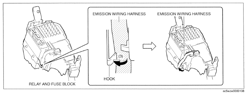
- While pressing the relay and fuse block hook in the direction of the arrow (3) shown in the figure, set the emission wiring harness away from the relay and fuse block hook.
 Courtesy of MAZDA MOTORS CORP.
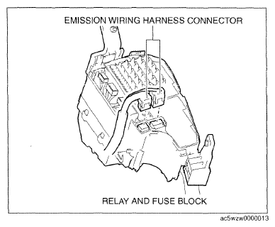
- Disconnect the emission wiring harness connectors.
 Courtesy of MAZDA MOTORS CORP.
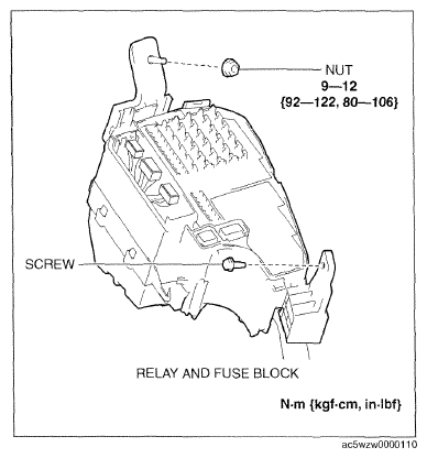
- Remove the nut and screw.
 Courtesy of MAZDA MOTORS CORP.
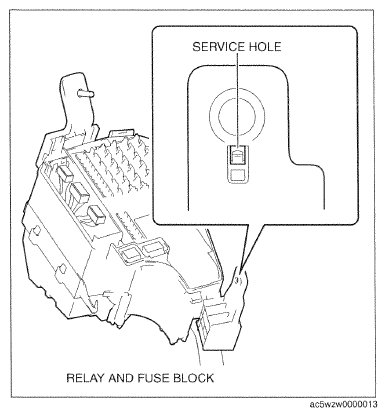
- Insert a tape-wrapped flathead screwdriver into the service hole in the position shown in the figure.
 Courtesy of MAZDA MOTORS CORP.
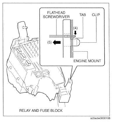
- While pressing the clip tab of the relay and fuse block in the direction of the arrow (4) shown in the figure, pull the clip in the direction of the arrow (5) to detach the clip tab from the engine mount.
 Courtesy of MAZDA MOTORS CORP.
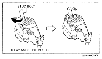
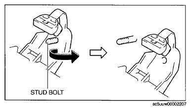
- Pull out the relay and fuse block from the stud bolt and set it aside as shown in the figure.
 Courtesy of MAZDA MOTORS CORP.
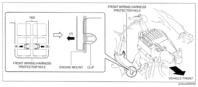
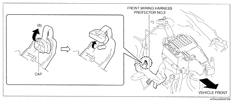
- While pressing the clip tabs of front wiring harness protector No. 2 in the direction of the arrows (6) shown in the figure, pull the clip in the direction of the arrow (7) shown in the figure to detach the clip tabs from the engine mount.
 Courtesy of MAZDA MOTORS CORP.
- Remove the front wiring harness protector No. 2 clip.
- Lift up the front wiring harness protector No. 2 cap in the direction of the arrow (8) shown in the figure.
 Courtesy of MAZDA MOTORS CORP.
- Pull out front wiring harness protector No. 2 from the stud bolt and set it aside as shown in the figure.
 Courtesy of MAZDA MOTORS CORP.
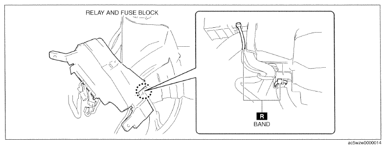
- Cut the band shown in the figure.
 Courtesy of MAZDA MOTORS CORP.
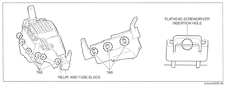
- Insert a flathead screwdriver into the gap between the relay and fuse block middle cover tabs and the relay and fuse block lower cover as shown in the figure.
 Courtesy of MAZDA MOTORS CORP.
- Move the flathead screwdriver in the direction of the arrow (9) shown in the figure, pull down the relay and fuse block lower cover in the direction of the arrow (10) shown in the figure, and detach the relay and fuse block middle cover tabs from the relay and fuse block lower cover.
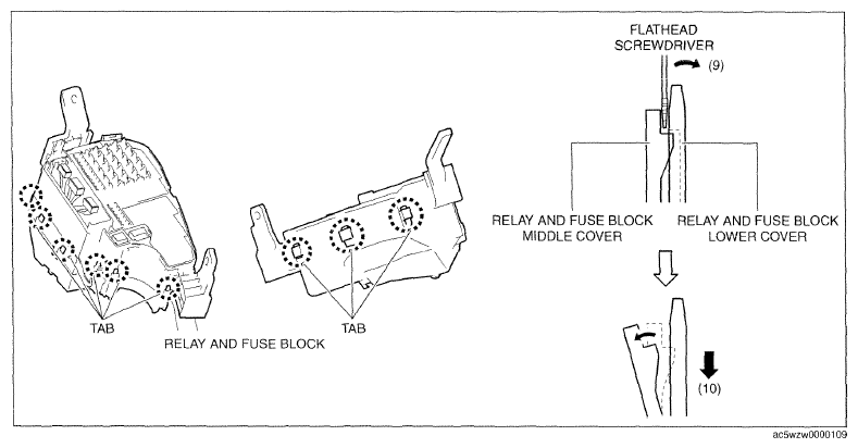 Courtesy of MAZDA MOTORS CORP.
- Detach all the relay and fuse block middle cover tabs from the relay and fuse block lower cover, and remove the relay and fuse block lower cover from the relay and fuse block middle cover. (See
RELAY AND FUSE BLOCK LOWER COVER INSTALLATION NOTE .)
- While pressing the wiring harness clip tabs in the direction of the arrows (11) shown in the figure, push out the clip in the direction of the arrow (12) shown in the figure to detach the clip tabs from the relay and fuse block.
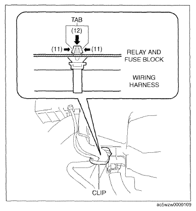 Courtesy of MAZDA MOTORS CORP.
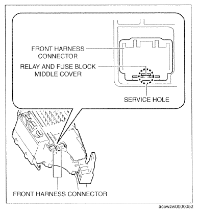
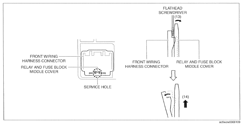
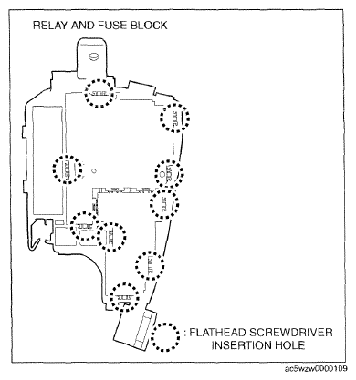
- Insert a flathead screwdriver into the service hole in the position shown in the figure.
- Move the flathead screwdriver in the direction of the arrow (13) shown in the figure, lift up the front wiring harness connectors in the direction of the arrow (14) shown in the figure, and detach the connector tabs from the relay and fuse block middle cover.
 Courtesy of MAZDA MOTORS CORP.
 Courtesy of MAZDA MOTORS CORP.
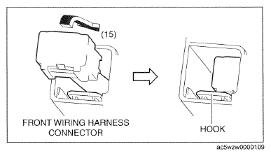
- Move the front wiring harness connector in the direction of the arrow (15) shown in the figure, release the hook, and pull it out from the relay and fuse block middle cover.
 Courtesy of MAZDA MOTORS CORP.
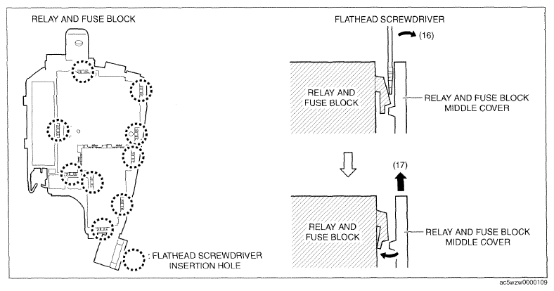
- Insert the flathead screwdriver into the gap between the relay and fuse block middle cover and the relay and fuse block shown in the figure.
- Move the flathead screwdriver in the direction of the arrow (16) shown in the figure, pull up the relay and fuse block middle cover in the direction of the arrow (17) shown in the figure, and detach the relay and fuse block tabs from the relay and fuse block middle cover.
 Courtesy of MAZDA MOTORS CORP.
 Courtesy of MAZDA MOTORS CORP.
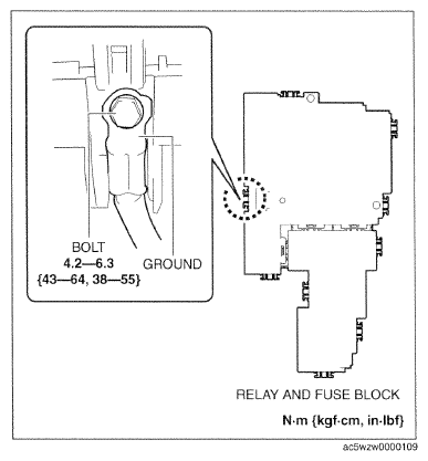
- Remove the bolt.
- Remove the ground.
 Courtesy of MAZDA MOTORS CORP.
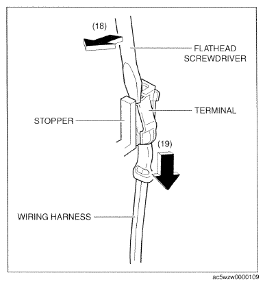
- Move the flathead screwdriver in the direction of the arrow (18) shown in the figure, pull the wiring harness in the direction of the arrow (19) while pressing the stopper, and detach the relay or fuse terminal from the stopper.
- Remove the relay or fuse terminal.
CAUTION:
- A terminal disconnection could cause electronic components and the system to not operate normally due to poor contact. After terminal relocation, lightly pull the wiring harnesses to verify that they cannot be pulled out
 Courtesy of MAZDA MOTORS CORP.
NOTE:
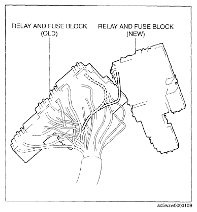
- For terminal relocation, line up the relays and fuse blocks of the old and news parts and always verify each of the wiring harnesses in the wiring diagram.
- Install in the reverse order of removal.
- Perform verify relay and fuse block replacement. (See
VERIFY RELAY AND FUSE BLOCK REPLACEMENT .)
 Courtesy of MAZDA MOTORS CORP.