Charging System (Service Information): Generator: Disassembly: Disassembly
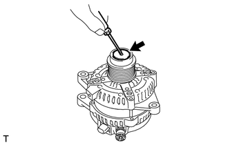
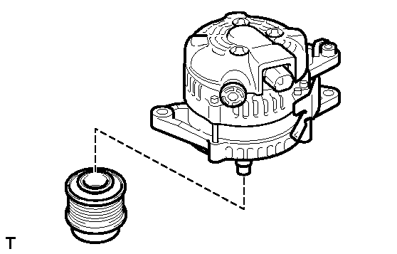
- REMOVE GENERATOR CLUTCH PULLEY
- Using a screwdriver, remove the generator pulley cap.
 Courtesy of © TOYOTA, LICENSE AGREEMENT TMS1002
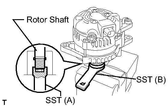
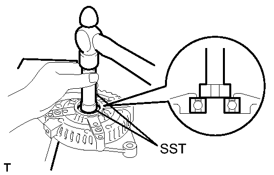
- Set SST (A) and (B).
 Courtesy of © TOYOTA, LICENSE AGREEMENT TMS1002
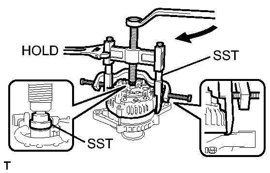
- Clamp SST (A) in a vise.
- Place the rotor shaft end into SST (A).
 Courtesy of © TOYOTA, LICENSE AGREEMENT TMS1002
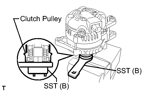
- Fit SST (B) onto the clutch pulley.
 Courtesy of © TOYOTA, LICENSE AGREEMENT TMS1002
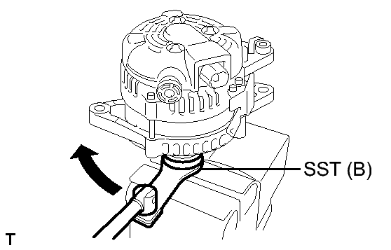
- Loosen the pulley by turning SST (B) in the direction shown in the illustration.
 Courtesy of © TOYOTA, LICENSE AGREEMENT TMS1002
- Remove the generator assembly from SST.
- Remove the clutch pulley from the rotor shaft.
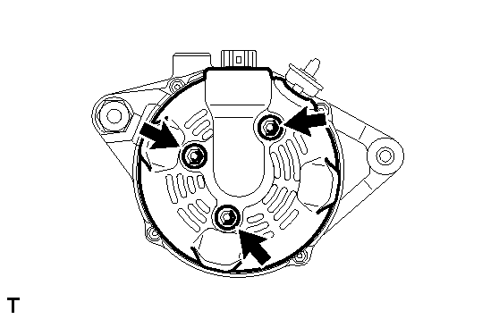
- REMOVE GENERATOR REAR END COVER
- Place the generator assembly on the clutch pulley.
 Courtesy of © TOYOTA, LICENSE AGREEMENT TMS1002
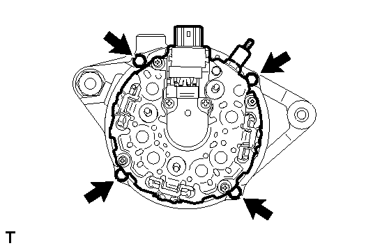
- Remove the 3 nuts and generator rear end cover.
 Courtesy of © TOYOTA, LICENSE AGREEMENT TMS1002
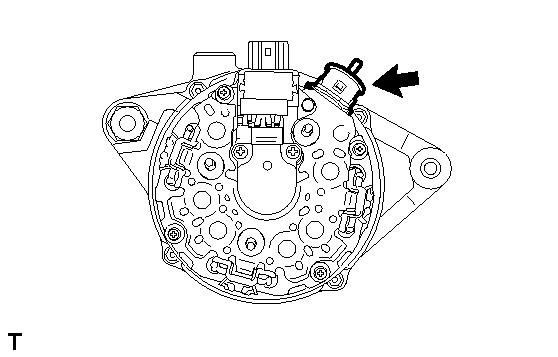
- REMOVE GENERATOR TERMINAL INSULATOR
- Remove the terminal insulator from the generator coil.
 Courtesy of © TOYOTA, LICENSE AGREEMENT TMS1002
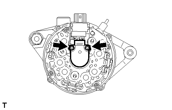
- REMOVE GENERATOR BRUSH HOLDER ASSEMBLY
- Remove the 2 screws and brush holder from the generator coil.
 Courtesy of © TOYOTA, LICENSE AGREEMENT TMS1002
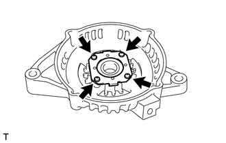
- REMOVE GENERATOR COIL ASSEMBLY
- Remove the 4 bolts.
 Courtesy of © TOYOTA, LICENSE AGREEMENT TMS1002
- Using SST, remove the generator coil assembly.
 Courtesy of © TOYOTA, LICENSE AGREEMENT TMS1002
- SST: 09950-40011
- 09951-04020
- 09952-04010
- 09953-04020
- 09954-04010
- 09955-04071
- 09957-04010
- 09958-04011
- REMOVE GENERATOR ROTOR ASSEMBLY
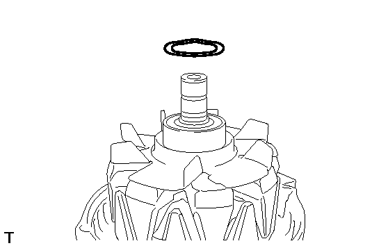
- Remove the generator washer.
 Courtesy of © TOYOTA, LICENSE AGREEMENT TMS1002
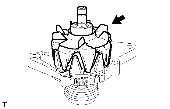
- Remove the generator rotor assembly.
 Courtesy of © TOYOTA, LICENSE AGREEMENT TMS1002
- REMOVE GENERATOR DRIVE END FRAME BEARING
- Remove the 4 screws and bearing retainer from the drive end frame.
 Courtesy of © TOYOTA, LICENSE AGREEMENT TMS1002
- Using SST and a hammer, tap out the drive end frame bearing from the drive end frame.
 Courtesy of © TOYOTA, LICENSE AGREEMENT TMS1002
- SST: 09950-60010
- SST: 09950-70010