Abs Indicator Light Malfunction
- Ensure ignition is off. Remove combination meter assembly. Inspect condition of ABS indicator light. Inspecting rear of meter assembly, ABS light is located 4th from right side of assembly. Replace as needed. If light is okay, check voltage at left meter harness connector (i18).
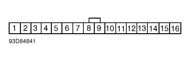
- Turn ignition on. Using voltmeter, measure voltage between combination meter harness connector terminal No. 13 and ground. See Fig 1
. If voltage is less than battery voltage, inspect and repair circuit as needed. See WIRING DIAGRAM at the end of this article. If battery voltage is present, turn ignition off and install combination meter.
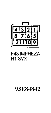
- Disconnect ABS control module and hydraulic unit harness connectors. See Figure
. Turn ignition on. Using voltmeter, measure voltage between ABS control unit harness connector terminal No. 29 and ground. Measure voltage between hydraulic unit harness connector terminal No. 10 and ground. See Fig 2
.
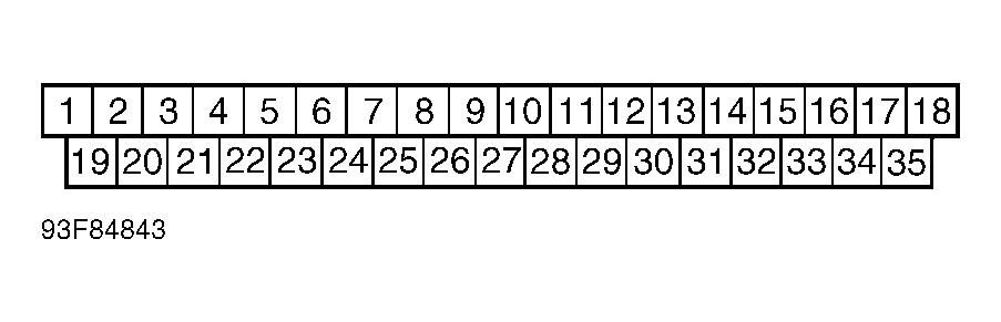
- If voltage is less than battery voltage, inspect and repair circuit as needed. See WIRING DIAGRAM at the end of this article. If battery voltage is present, turn ignition off. Using ohmmeter, check continuity between ABS harness connector terminals No. 10, 20 and 34, and ground. See Fig 3
. If continuity does not exist, inspect and repair circuit as needed.
- If continuity exists, connect ABS harness connector. Check continuity between hydraulic unit harness connector terminal No. 8 and ground. See Fig 2
. If continuity does not exist, inspect and repair circuit as needed. If continuity exists, remove hydraulic unit valve relay.
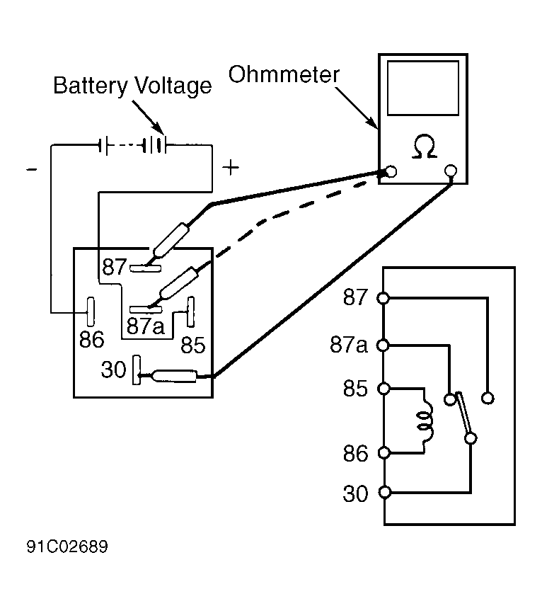
- Hydraulic unit valve relay (5 terminal) is located on hydraulic unit. Check continuity of relay. See Fig 4
. Check resistance between relay terminals 85 and 86. Resistance should be 93-113 ohms. Replace relay if measurements and/or continuity is not as specified. If relay is okay, replace ABS control unit and hydraulic unit. See REMOVAL & INSTALLATION.
 Courtesy of SUBARU OF AMERICA, INC.
 Courtesy of SUBARU OF AMERICA, INC.
 Courtesy of SUBARU OF AMERICA, INC.
 Courtesy of SUBARU OF AMERICA, INC.