Test 9: Motor Relay Circuit Problem
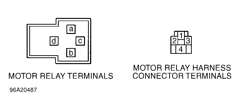
- Turn ignition off. Remove motor relay from hydraulic unit. Connect positive lead of ohmmeter to relay terminal "a". Connect negative lead to relay terminals "b". See Fig 1
. If resistance is about 57 ohms, go to next step. If resistance is not about 57 ohms, replace relay.
 Courtesy of SUBARU OF AMERICA, INC.
- Measure voltage between ground and terminal No. 1 at relay harness connector. Battery voltage should be present. Measure voltage between ground and terminal No. 3 at relay harness connector. Voltage should be zero volts. If voltage is as specified, go to next step. If voltage is not as specified, repair wiring harness as necessary. Turn ignition on. Measure voltage between ground and terminals No. 1 and 3 at relay harness connector. Battery voltage should be present at both terminals. If battery voltage exists, go to next step. If battery voltage does not exist, repair wiring harness as necessary.
- Turn ignition off. Disconnect ABS/TCS control unit connectors. Measure resistance between ground and terminal No. 9 at ABS/TCS control unit 16-pin harness connector. See Figure
. If resistance is infinite, go to next step. If resistance is not infinite, repair wiring harness as necessary.
- Install motor relay. Connect negative lead of ohmmeter to terminal No. 9 at ABS/TCS control unit 16-pin connector. Connect positive lead to ground. If resistance is 51-63 ohms, go to next step. If resistance is not 51-63 ohms, repair wiring harness as necessary.
- Connect ABS/TCS control unit connectors. Perform sequence control. See SEQUENCE CONTROL
under SELF-DIAGNOSTICS. Listen for hydraulic unit motor operation. If motor operates, go to next step. If motor does not operate, go to step 10).
- Turn ignition off. Disconnect motor sensor 2-pin connector (Blue/Yellow wire and Red/White wire) from hydraulic unit. Measure resistance between motor sensor 2-pin connector terminals (at hydraulic unit). If resistance is 72-98 ohms, go to next step. If resistance is not 72-98 ohms, replace hydraulic unit.
- Measure resistance between ground and each terminal of motor sensor 2-pin connector (at hydraulic unit). If both resistance readings are infinite, go to next step. If any resistance reading is not infinite, replace hydraulic unit.
- Reconnect motor sensor 2-pin connector. Disconnect ABS/TCS control unit connectors. Measure resistance between terminals No. 3 and 13 at ABS/TCS control unit 20-pin connector. If resistance is 72-98 ohms, go to next step. If resistance is not 72-98 ohms, repair wiring harness as necessary.
- Measure resistance between ground and terminals No. 3 and 13 at ABS/TCS control unit 20-pin connector. If both resistance readings are infinite, go to next step. If either resistance reading is not infinite, repair wiring harness as necessary.
- Reconnect ABS/TCS control unit connectors. Perform sequence control. See SEQUENCE CONTROL
under SELF-DIAGNOSTICS. Listen for hydraulic unit motor operation. While TCS operating indicator light is on, measure voltage between ground and terminal No. 4 at motor relay harness connector. See Fig 1
. If battery voltage exists, go to next step. If battery voltage does not exist, replace motor relay.
- Turn ignition off. Disconnect motor relay. Disconnect hydraulic motor 2-pin connector (Black wire and White wire) from hydraulic unit. Measure resistance of White wire between terminals No. 2 at motor 2-pin harness connector and No. 4 at motor relay harness connector. If resistance is less than one ohm, go to next step. If resistance is more than one ohm, repair wiring.
- Measure resistance between ground and terminal No. 2 (White wire) at hydraulic motor 2-pin harness connector. If resistance is infinite, go to next step. If resistance is not infinite, repair wiring as necessary.
- Measure resistance between ground and terminal No. 1 (Black wire) at hydraulic motor 2-pin harness connector. If resistance is more than 1 ohm, repair motor ground circuit in wiring harness. If resistance is 1 ohm or less, replace hydraulic unit.