- Release the fuel pressure. < Ref. to
RELEASING OF FUEL PRESSURE , PROCEDURE, Fuel.>
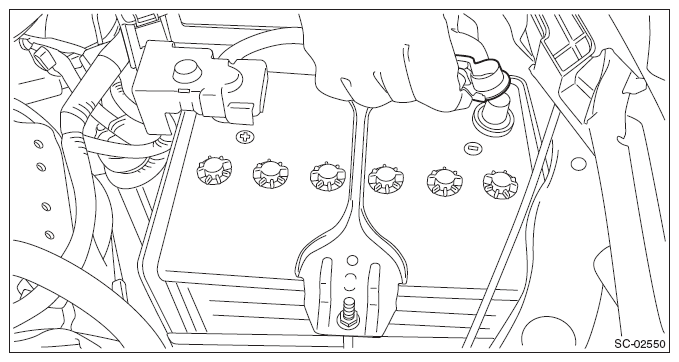
- Disconnect the ground cable from battery.
 Courtesy of SUBARU OF AMERICA, INC.
- Open the fuel filler lid and remove the fuel filler cap.
- Lift up the vehicle.
- Remove the under cover. < Ref. to
REMOVAL
, Front Under Cover.>
- Drain approximately 3.0 L (3.2 US qt, 2.6 Imp qt) of coolant. < Ref. to
DRAINING OF ENGINE COOLANT
, REPLACEMENT, Engine Coolant.>
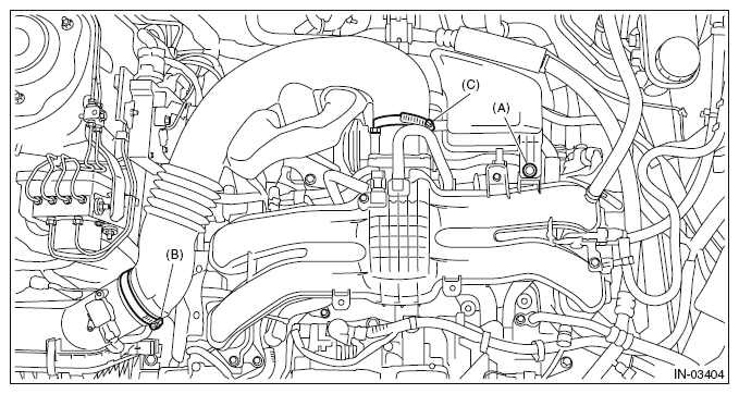
- Remove the clip (A) from the air intake boot.
- Loosen the clamp (B) connecting the air intake boot and air cleaner case (rear).
- Loosen the clamp (C) which connects the air intake boot and throttle body.
 Courtesy of SUBARU OF AMERICA, INC.
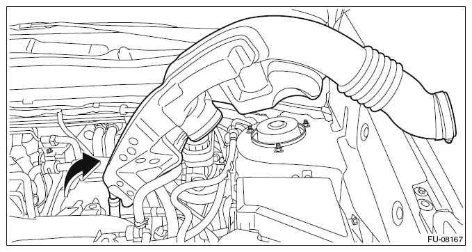
- Remove the air intake boot from the throttle body, and move it to the left side wheel apron.
 Courtesy of SUBARU OF AMERICA, INC.
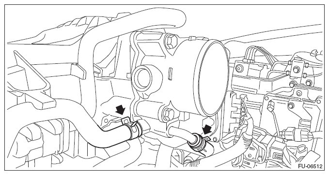
- Disconnect the preheater hose from throttle body.
 Courtesy of SUBARU OF AMERICA, INC.
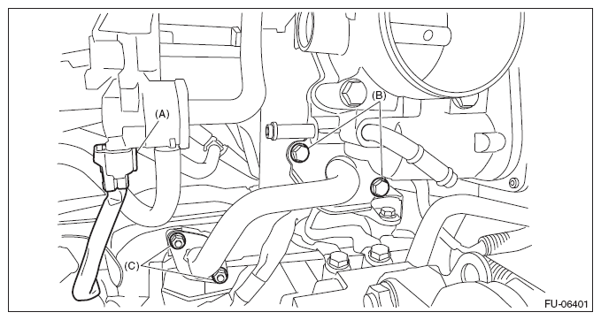
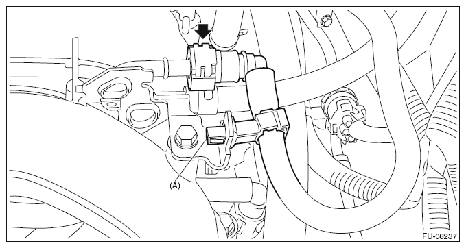
- Disconnect the connector (A) from the purge control solenoid valve.
- Loosen the bolt (B) which secures the EGR pipe to the intake manifold.
- Remove the nut (C) which holds EGR pipe from the water pipe assembly.
 Courtesy of SUBARU OF AMERICA, INC.
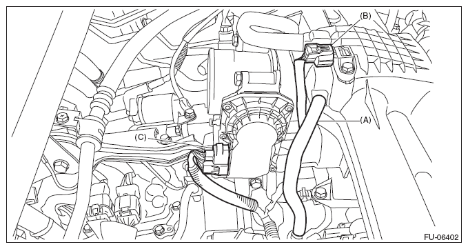
- Disconnect the PCV hose (A) from intake manifold.
- Disconnect the connector (B) from manifold absolute pressure sensor.
- Disconnect the connector (C) from the throttle position sensor.
 Courtesy of SUBARU OF AMERICA, INC.
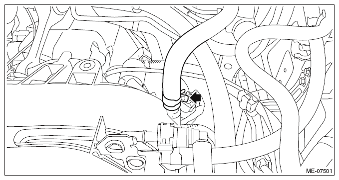
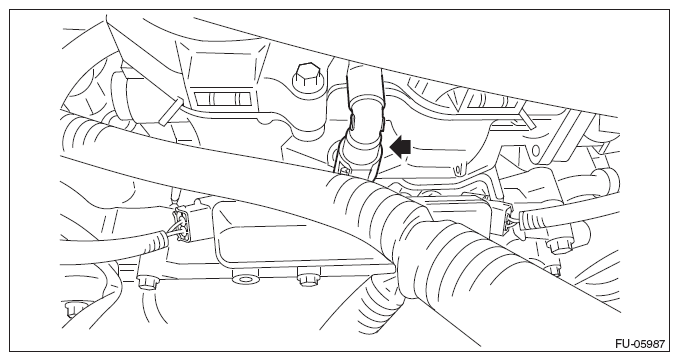
- Disconnect the brake booster vacuum hose from the intake manifold.
 Courtesy of SUBARU OF AMERICA, INC.
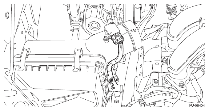
- Disconnect the connector (A) from the mass air flow and intake air temperature sensor, and remove the clip (B) which holds the mass air flow and intake air temperature sensor harness.
 Courtesy of SUBARU OF AMERICA, INC.
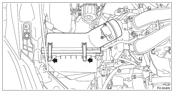
- Remove the air cleaner case (rear).
 Courtesy of SUBARU OF AMERICA, INC.
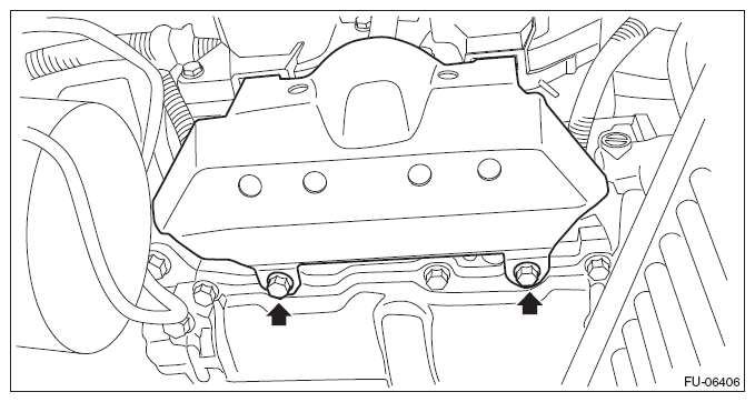
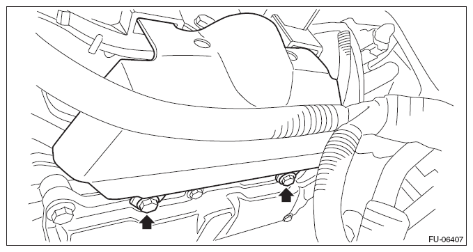
- Remove the intake manifold protector RH.
 Courtesy of SUBARU OF AMERICA, INC.
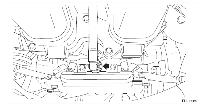
- Disconnect the fuel delivery pipe from the fuel pipe RH.
CAUTION:
- Be careful not to spill fuel.
- Catch the fuel from the pipes using a container or cloth.
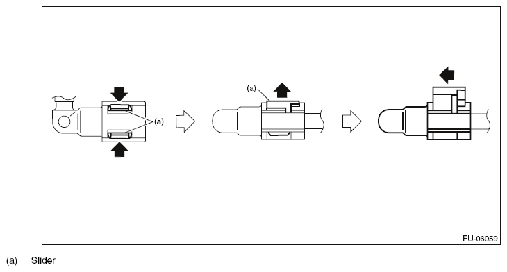
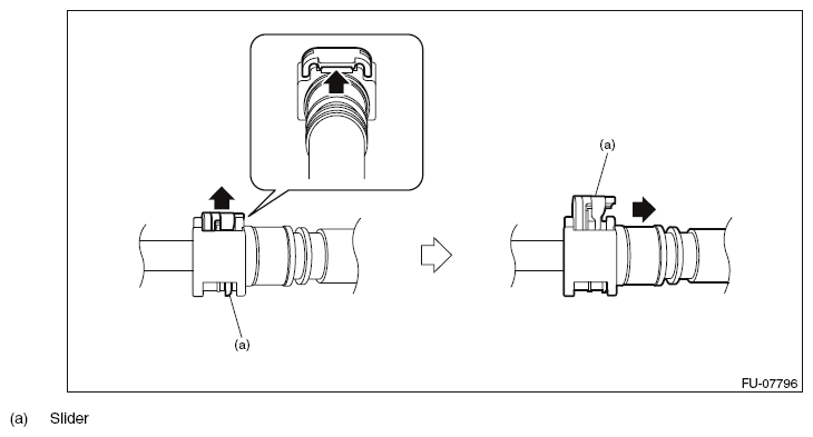
NOTE:
Disconnect the quick connector as shown in the figure.
 Courtesy of SUBARU OF AMERICA, INC.
 Courtesy of SUBARU OF AMERICA, INC.
- Remove the intake manifold protector LH.
 Courtesy of SUBARU OF AMERICA, INC.
- Disconnect the fuel delivery pipe from the fuel pipe LH.
CAUTION:
- Be careful not to spill fuel.
- Catch the fuel from the pipes using a container or cloth.
NOTE:
Disconnect the quick connector as shown in the figure.
 Courtesy of SUBARU OF AMERICA, INC.
 Courtesy of SUBARU OF AMERICA, INC.
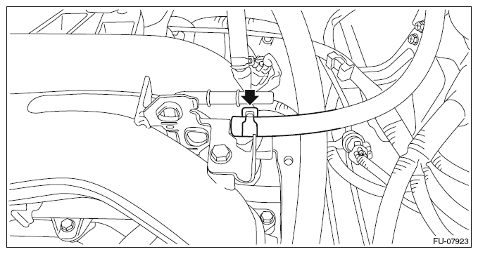
- Disconnect the fuel delivery tube and evaporation hose.
CAUTION:
- Be careful not to spill fuel.
- Catch the fuel from the tubes using a container or cloth.
- Disconnect the quick connector on the fuel delivery tube from the fuel pipe assembly, and remove the clip (A) securing the fuel delivery tube.
NOTE:
Disconnect the quick connector as shown in the figure.
 Courtesy of SUBARU OF AMERICA, INC.
 Courtesy of SUBARU OF AMERICA, INC.
- Disconnect the evaporation hose from the fuel pipe assembly.
 Courtesy of SUBARU OF AMERICA, INC.
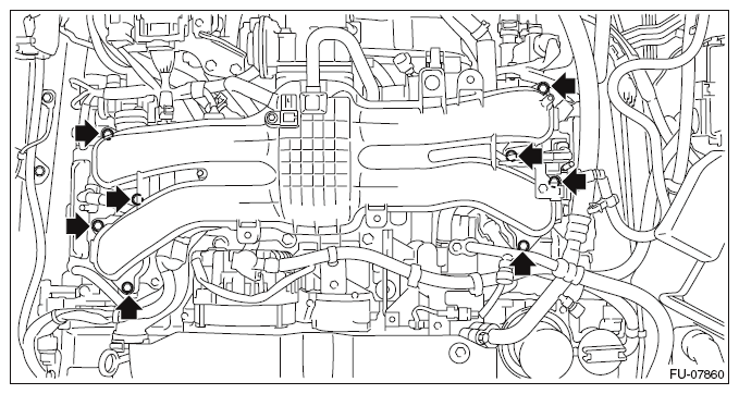
- Remove the intake manifold from the tumble generator valve assembly.
 Courtesy of SUBARU OF AMERICA, INC.
- Remove the engine wiring harness. < Ref. to
REMOVAL , Engine Wiring Harness.>