Shift Cable Replacement
- Raise the vehicle on a lift, or apply the parking brake, block rear wheels, and raise the front of the vehicle. Make sure it is securely supported.
- Remove the center console (see
CENTER CONSOLE REMOVAL/INSTALLATION
).
- Move the shift lever to N.
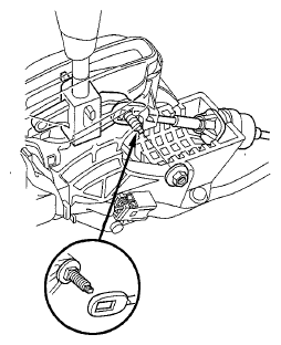
- Remove the nut securing the shift cable end.
 Courtesy of AMERICAN HONDA MOTOR CO., INC.
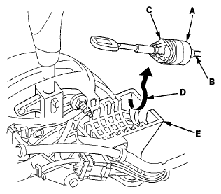
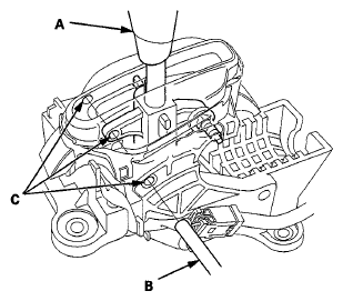
- Rotate the socket holder (A) on the shift cable (B) a quarter turn; the corner (C) on the socket holder will be in the opening (D) of the shift lever bracket base (E). Then slide the socket holder to remove the shift cable from the bracket.
 Courtesy of AMERICAN HONDA MOTOR CO., INC.
- Remove the air cleaner (see
AIR CLEANER REMOVAL/INSTALLATION
).
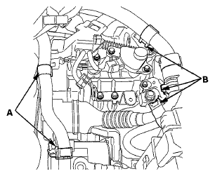
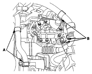
- Remove the heater hose clamps (A) and the IMA power cable clamps (B) from the bracket.
 Courtesy of AMERICAN HONDA MOTOR CO., INC.
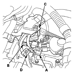
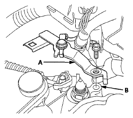
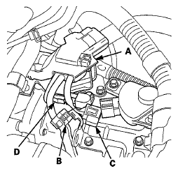
- Disconnect the transmission range switch connector (A) and the CVT output shaft (driven pulley) speed sensor connector (B).
 Courtesy of AMERICAN HONDA MOTOR CO., INC.
- Remove the harness clamp (C) and the harness holder clamp (D) from the harness clamp bracket.
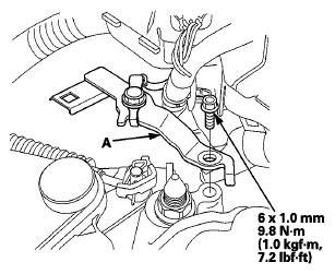
- Remove the ground terminal bracket (A) from the transmission mount (B).
 Courtesy of AMERICAN HONDA MOTOR CO., INC.
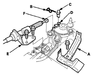
- Remove the harness clamp bracket (A).
- Remove the snap pin (B) and the control pin (C) from the control lever (D).
 Courtesy of AMERICAN HONDA MOTOR CO., INC.
- Remove the bolts securing the shift cable holder (E), then separate the shift cable (F) from the control lever.
- Remove the heat shield from under the body.
- Remove the nut securing the shift cable bracket (A).
 Courtesy of AMERICAN HONDA MOTOR CO., INC.
- Remove the shift cable grommet (B), and pull out the shift cable (C).
- Insert a new shift cable through the grommet hole (D), and install the grommet in its hole. Do not bend the shift cable excessively.
- Secure the shift cable bracket with the nut.
- Install the heat shield.
- Secure the shift cable holder on the transmission with the bolts.
- Install the harness clamp bracket.
- Apply molybdenum grease to the hole in the shift cable end collar (A). Attach the shift cable end to the selector control lever (B). Insert the control pin (C) through the selector control lever hole (D), through the shift cable end hole, and into the selector control lever slotted hole (E) in the direction shown. Push the control pin until its flange (F) contacts the selector control lever surface.
 Courtesy of AMERICAN HONDA MOTOR CO., INC.
- Insert the snap pin (G) in the direction show through the control pin hole and out the opening (H) of the selector control lever so that the hooked end (I) of the snap pin snaps into the countersunk hole (J) of the control pin.
- Install the ground terminal bracket (A).
 Courtesy of AMERICAN HONDA MOTOR CO., INC.
- Install the harness clamps (A) and the harness holder clamp (B).
 Courtesy of AMERICAN HONDA MOTOR CO., INC.
- Connect the transmission range switch connector (C) and the CVT output shaft (driven pulley) speed sensor connector (D).
- Install the harness hose clamps (A) and IMA power cable clamp (B).
 Courtesy of AMERICAN HONDA MOTOR CO., INC.
- Install the air cleaner (see
AIR CLEANER REMOVAL/INSTALLATION
).
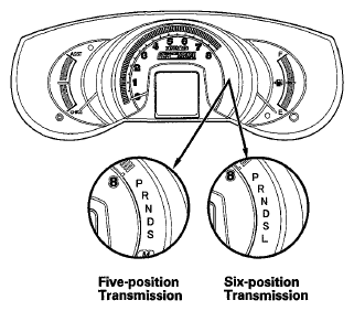
- Turn the ignition switch to ON (II), and check that the N indicator comes on.
 Courtesy of AMERICAN HONDA MOTOR CO., INC.
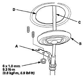
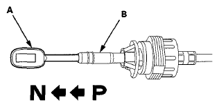
- If necessary, push the shift cable (A) until it stops, then release it. Pull the shift cable back two steps so that the shift position is in N. Do not hold the shift cable guide (B) to adjust the shift cable.
 Courtesy of AMERICAN HONDA MOTOR CO., INC.
- Turn the ignition switch to LOCK (0).
- Place the shift lever in N (A), then insert a 6.0 mm (0.24 in) pin (B) into the positioning holes (C) on the shift lever bracket base and into the positioning hole on the shift lever. Use only a 6.0 mm pin that is free of burrs.
 Courtesy of AMERICAN HONDA MOTOR CO., INC.
- Check that the shift lever is secured in N.
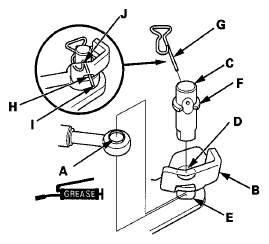
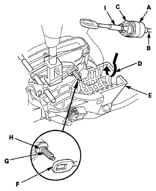
- Rotate the socket holder (A) on the shift cable (B) to place the corner (C) on the holder opposite the opening (D) in the shift lever bracket base (E). Align the holder with the opening in the bracket, then slide the holder into the bracket. Install the shift cable end (F) over the mounting stud (G) by aligning its square hole with the square fitting (H) at the bottom of the stud. Rotate the holder a quarter turn until the holder stops to secure the shift cable. Do not install the shift cable by holding the shift cable guide (I).
 Courtesy of AMERICAN HONDA MOTOR CO., INC.
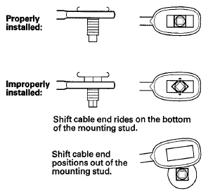
- Check that the shift cable end is properly installed on the mounting stud.
 Courtesy of AMERICAN HONDA MOTOR CO., INC.
- If the cable end is out of position on the mounting stud, remove the shift cable from the bracket, and reinstall the shift cable. Do not install the shift cable end on the mounting stud while the shift cable in on the bracket. If the cable end rides on the bottom of the mounting stud, rotate the stud and align the square fitting with the hole.
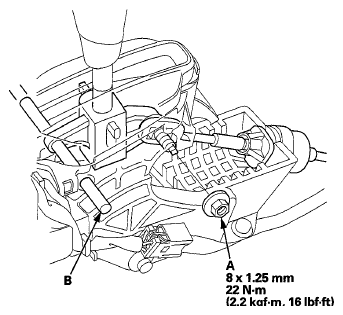
- Secure the shift cable end with the nut (A).
 Courtesy of AMERICAN HONDA MOTOR CO., INC.
- Remove the 6.0 mm (0.24 in) pin (B) that was installed to hold the shift lever.
- Turn the ignition switch to ON (II). Move the shift lever to each position, and check that the A/T gear position indicator follows the transmission range switch.
- Shift the shift lever to P, and check that the shift lock works properly. Push the shift lock release, and check that the shift lever releases, and also check that the shift lever locks when it is shifted back into P.
- Install the center console (see
CENTER CONSOLE REMOVAL/INSTALLATION
).